
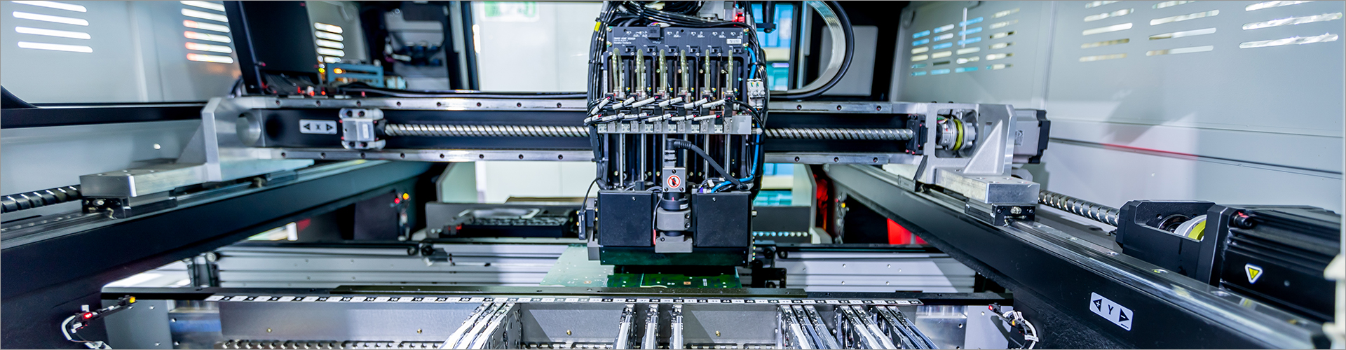

Servo Power Head Selection Guide for Automated Drilling, Tapping, and Milling
Servo Power Head Selection Guide for Automated Drilling, Tapping, and Milling
I select a Servo Power Head by matching the machining load, spindle requirements, servo control, machine structure, and integration conditions—not by choosing the highest-rated unit alone. For automated drilling, tapping, and milling, the most important checks are available torque and speed, tool size, axial control, rigidity, cooling, accuracy requirements, and maintenance access. In this guide, I explain how I evaluate these factors and how HAEGOLIA can support equipment manufacturers, engineers, and purchasing teams with mechanical parts and fabrication services.
If you want to learn more, please visit our website.
Key Takeaways
- I first define the material, tool, cutting load, cycle time, and required machining result.
- I then compare servo motor capacity, spindle speed, torque, axial feed control, rigidity, and mounting dimensions.
- For reference, a buyer may specify a target such as repeatability of ±0.01 mm, an operating duty of 8 hours per shift, or coolant delivery near 20 bar; these are application requirements to validate, not universal Servo Power Head specifications.
- I also confirm electrical interfaces, PLC communication, lubrication, coolant routing, guarding, spare parts, and supplier engineering support before ordering.
Who This Guide Is For
I prepared this guide for automated equipment builders, CNC integrators, production engineers, maintenance teams, and procurement professionals. It is especially useful when a project requires a compact machining unit that can be installed on a transfer line, special-purpose machine, robotic cell, or custom fabrication system. It can also help buyers compare standard and customized spindle attachments before requesting a quotation.
My recommendations apply to applications such as hole making, thread production, spot facing, countersinking, light milling, and other controlled machining operations. The correct selection still depends on the actual workpiece, cutting tools, fixture design, and machine architecture. I therefore recommend treating this article as a technical screening framework rather than a substitute for application validation.
What a Servo Power Head Does
A Servo Power Head is a driven machining unit that combines a spindle or tool-holding assembly with a servo-controlled drive system. Depending on its design, it can rotate a drill, tap, reamer, cutter, or other tool while supporting controlled speed, positioning, and feed motion. In an automated machine, the unit is usually integrated with a frame, slide, actuator, fixture, controller, and safety system.
Core Functions and Applications
I use Servo Power Heads when the process requires more control than a simple fixed-speed motor can provide. Servo control can support programmed speed changes, coordinated feed, position monitoring, and controlled acceleration or deceleration when the drive, motor, controller, and mechanical transmission are properly matched. These functions are valuable for repeatable drilling, synchronized tapping, and controlled milling operations.
- Drilling: The unit should provide appropriate spindle speed, axial feed, tool retention, and chip evacuation for the selected drill and material.
- Tapping: The control system and mechanical structure must support the required thread pitch, synchronization method, reversing action, and torque management.
- Milling: The head requires sufficient rigidity, bearing support, torque, and resistance to cutting-force variation.
- Multi-operation automation: A programmable unit may help integrate several machining steps into one production sequence, subject to cycle-time and process validation.
Types, Materials, and Configuration Options
I normally compare Servo Power Heads by drive arrangement, spindle orientation, mounting method, and application duty. Common configurations include horizontal, vertical, fixed, slide-mounted, single-spindle, and multi-spindle arrangements. A multi-spindle solution can be useful when several holes must be processed together, but it may require more detailed synchronization, tooling, and fixture analysis.
Material selection affects housing strength, weight, wear resistance, and thermal behavior. Machined steel or cast metal structures may be selected where rigidity and load resistance are priorities, while aluminum components may be suitable for weight-sensitive covers or selected structural parts after engineering review. Bearing seats, spindle interfaces, mounting faces, and sliding surfaces require particular attention because dimensional stability and alignment influence machining performance.
Key Specifications I Review
Spindle and Servo Performance
I begin with the required spindle speed range, continuous and peak torque, motor power, acceleration, and duty cycle. These values must be calculated from the tool diameter, cutting speed, feed, material, depth of cut, and expected production rate. A larger motor is not automatically better because excess capacity can increase cost, inertia, electrical demand, and integration complexity.
For tapping, I verify how the servo system handles speed reversal and thread synchronization. For milling, I focus more closely on torque stability and mechanical rigidity under changing cutting forces. For drilling, I assess the relationship between spindle speed, axial feed, coolant access, chip evacuation, and tool life.
Accuracy, Rigidity, and Cooling
I separate positioning accuracy, repeatability, spindle runout, and machining accuracy because they describe different performance factors. For example, a project may set an illustrative repeatability target of ±0.01 mm, but the final result also depends on fixture stability, tool condition, thermal expansion, workpiece variation, and machine calibration. I ask the supplier to clarify which values are design targets, inspection values, or application-dependent results.
If you want to learn more, please visit our website HAEGOLIA.
Rigidity is equally important for milling and larger-diameter drilling. I review bearing arrangement, spindle overhang, housing construction, mounting-face flatness, slide support, and the load path into the machine frame. Cooling may include air, external coolant, or through-spindle delivery; if a project considers a coolant pressure of 20 bar, I confirm that the spindle, seals, hoses, filtration, and machine enclosure are designed for that condition.
My Servo Power Head Selection Framework
Step 1: Define the Machining Requirement
I record the workpiece material, hardness or condition, hole diameter, thread size, milling cutter, cutting depth, tolerance, surface requirement, and cycle time. I also identify whether the operation is intermittent or continuous, because a unit used for an 8-hour shift may require different thermal and maintenance planning than one used occasionally. I include coolant, chip control, tool-change requirements, and access for inspection at this stage.
Step 2: Match the Head to the Cutting Load
I calculate or obtain the required speed, feed, torque, and power from the cutting-tool manufacturer or process engineer. I then compare those requirements with the proposed Servo Power Head under both normal and peak conditions. I avoid selecting from motor power alone, since spindle bearings, transmission efficiency, tool holding, and structural stiffness can limit the usable machining capacity.
Step 3: Check Integration Requirements
I confirm mounting dimensions, spindle nose, tool interface, overall envelope, cable routing, coolant connections, lubrication access, and guarding. I also check the servo drive, encoder or feedback arrangement, controller communication, emergency-stop behavior, and commissioning procedure. A technically suitable head can still create delays if its mechanical and electrical interfaces do not match the automation platform.
Step 4: Validate the Process Before Volume Purchase
I recommend a drawing review and, where practical, a sample or application test using the real workpiece and tooling. The validation should examine hole position, thread quality, burr formation, surface finish, cycle time, temperature, vibration, and chip evacuation. I document the acceptance criteria before production procurement so that the buyer, machine builder, and supplier share the same definition of success.
Common Selection Mistakes
- Choosing a spindle only by maximum speed while ignoring torque at the actual operating range.
- Assuming servo control alone guarantees tapping accuracy without confirming synchronization and tooling conditions.
- Underestimating fixture deflection, machine-frame vibration, or spindle overhang during milling.
- Leaving coolant routing, chip removal, lubrication, and maintenance access until after the layout is frozen.
- Requesting a quotation without providing workpiece drawings, tool information, cycle requirements, and interface constraints.
Pricing, MOQ, and Lead-Time Considerations
Servo Power Head pricing depends on the motor and drive, spindle arrangement, tooling interface, sensors, housing design, cooling, mounting customization, testing, and required documentation. Standardized configurations may be easier to quote, while custom housings, special spindle noses, or integrated fabrication work normally require engineering review. I do not treat a low initial price as the lowest total cost if it creates redesign, commissioning, or maintenance risks.
Minimum order quantity and lead time should be discussed together with prototype requirements. A buyer may request one development unit, a pilot batch, or a production quantity, and each option can involve different setup, machining, inspection, and procurement conditions. I recommend confirming drawing approval, revision control, packaging, spare-part availability, and after-sales response before placing a purchase order.
How I Evaluate a Supplier
Supplier Evaluation Checklist
- Can the supplier review cutting data and recommend a suitable configuration?
- Can the supplier provide dimensional drawings, interface details, and revision-controlled documentation?
- Are machining, assembly, inspection, and fabrication capabilities coordinated under one project process?
- Can the supplier discuss spindle performance, servo integration, cooling, lubrication, and maintenance requirements?
- Are prototype support, sample validation, packaging, spare parts, and communication responsibilities clearly defined?
As HAEGOLIA, I support B2B buyers through mechanical parts and fabrication services related to CNC machining units and spindle attachments. Depending on the project, our support can include design-for-manufacturing feedback, machined components, customized mounting parts, housing fabrication, and coordination of application requirements. I recommend sending the workpiece material, tool list, target cycle time, drawings, machine layout, and control requirements so that our engineering team can review the Servo Power Head opportunity with specific information.
Conclusion and Next Steps
The best Servo Power Head for automated drilling, tapping, or milling is the one that matches the real cutting load, control method, spindle behavior, machine structure, and production environment. I recommend defining process data first, checking torque and rigidity rather than power alone, confirming mechanical and electrical integration, and validating the application before committing to volume. Cooling, maintenance, documentation, and supplier support should be treated as part of the solution rather than optional details.
For the next step, prepare your workpiece drawing, material, tool specifications, machining sequence, target tolerance, cycle-time objective, mounting space, and control-platform information. Share these requirements with HAEGOLIA for a practical review of the Servo Power Head, CNC machining unit, spindle attachment, and related fabrication needs. This approach helps reduce selection risk and creates a clearer path from initial concept to dependable automated equipment.
For more information, please visit Servo Power Head(th,tr,ru).
The Servo Power Head is an integral component of advanced CNC machining units and spindle attachments, enhancing precision and efficiency in manufacturing processes by allowing for fine adjustments and control over tooling angles, ultimately improving the quality of machined parts and reducing cycle times in various applications. CNC Machining Units & Spindle Attachments
70
0
0
Comments
All Comments (0)